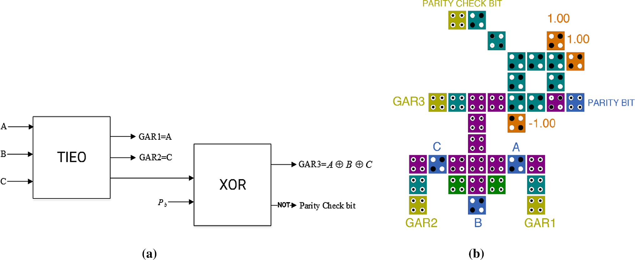

In order to implement a function that would check for correctness in the parity of an input signal, we first created a truth table and an associated Karnaugh map for the circuit.

After the circuit was completed, the six outputs of the circuit were connected to the corresponding wires on a model traffic light to test whether the pattern generated by the circuit was correct. These equations and how they were obtained are detailed in the section that follows.Īfter obtaining the individual functions that defined the pattern of lighting for the different outputs, the circuit was then implemented on a breadboard. This time, however, the output was considered active low, or when the value is 0, when looking at the truth tables and Karnaugh map. An equation was obtained for North/South Red, East/West Red, North/South Yellow, and so on for all six outputs. In order to obtain the functions that describe the system, a truth table and Karnaugh map was made for all the different outputs of the system.

These binary values provided by the counter made up the four inputs to the system. A binary counter was used and set up to provide a continuous and repeating signal, ranging from 0 to 15 in binary form. If the input was not a prime number, the output would be low and the LED would not light.įor this task, a circuit was designed to output a traffic light signal pattern for a 4-way intersection. If the input was a prime number, then the output would be high and the LED would light.
Parity checker circuit series#
A series of on-off switches were used to represent and control the binary input to the circuit and the output was displayed on a LED on the breadboard. Using this equation, a logic circuit was constructed on a breadboard. The following equation was obtained from the Karnaugh map. To begin, a truth table was created and the inputs and output are placed in their corresponding spots in the Karnaugh map. Once again, each digit in the binary number is taken as a single input and passed through the circuit. The output of the function was displayed on one of the LEDs on the breadboardĪ circuit was designed to determine whether or not a number that was inputted in binary form was a prime number. When there is an even number of 1's, the output is low or "0". The output of this system is a single binary digit that is high when there is an uneven number of 1's in the five binary values of the input, and signals that the parity bit is in error. This equation was then implemented on a breadboard using XOR gates. The function that was obtained is f = A XOR B XOR C XOR D XOR P, where A, B, C, and D represent the four binary digits and P represents the parity bit. From the Karnaugh map, an equation describing a possible circuit design for the system was extracted. The function of this system was obtained by constructing a truth table from the inputs to the system, and then translating it into a Karnaugh map. Each digit in the binary number is an input to the system and the fifth input is provided by the parity bit. For example, the number "3" in decimal form would be "0011" in binary form. The 4-bit binary number is a binary representation of the numbers 0 throughġ5 in the decimal system. These inputs were a 4-bit binary number and one even parity bit. For the second task, a digital circuit was designed and built to output the proper signaling sequence for a 4-way intersection.įor the parity checker, a total of 5 binary values made up the inputs to the circuit. Another circuit was made to check whether or not a four-bit binary number was a prime number. A circuit was designed in such a way that the number of 1's in the 4-bit binary number should be even when the parity bit is included. For the first task, we built a parity checker which took as its inputs, a 4-bit binary number and one even parity bit.


 0 kommentar(er)
